Analysis of the Bentwaters Slow Targets - Part 2
An Opinion by Martin Shough
a) Sporadic AP
b) Sidelobe Returns and Multiple Reflections
c) Radio Frequency Interference & Deception Jamming
d) Partial Reflection from Elevated Layers
Track D, 2100*-2155Z.
[* IR-1-56 gives 2130.
Internal and independent evidence discussed in the text indicates that this is almost certainly in error.]
a.) Sporadic AP Returns from Ground Targets and Surface Vehicles
A surveillance radar will have its own characteristic pattern of permanent clutter, a region of ground echoes a few miles in radius around the site. These reflections are unavoidable if the beam is required to fill a large surveillance volume, and indeed the energy scattered forward is exploited in the shaping of the beam. During superrefractive AP conditions the area of clutter will tend to expand. This clutter is typically widespread and rather amorphous, but there could be rare occasions when sporadic ground echoes due to changing propagation conditions generated brief, coherent targets from different ground reflectors successively, displaced from scan to scan in such a way that they appeared to be returns from a single moving target or group of targets. Unlike returns via scattering from elevated layers, where the pattern of moving structures associated with the layer could impose pattern on incoherent reflections back-scattered from a broad area of terrain (see Sections d. & e. below), sporadic AP returns from stationary ground targets will be just that - sporadic - and any consistent pattern appearing over a number of scans will be a result of chance or the operator's imagination.
In the present case it seems altogether improbable that the highly structured Track D, with consistency of heading, of presentation, of the cluster's axial orientation and of its ordered ultrastructure, could be due to this mechanism over the space of several tens of minutes and many hundreds of antenna rotations.
Moving surface vehicles might be detected as isolated point targets, and if propagation conditions are unusually anisotropic such targets might be restricted to a narrow azimuth range. In the present case ground vehicles (such as trucks, which can make excellent corner reflectors) are ruled out for obvious reasons, including speed, disregard of the Suffolk road network and the fact that a major portion of the track falls over the sea. Surface ships would seem to be ruled out for the equally obvious reason that a major part of the track is over land. However, due to the phenomenon of multiple-trip returns it is possible in AP conditions for radar to display echoes from surface targets which are far beyond the unambiguous range of the set.
Unambiguous range is determined by the pulse repetition frequency. After each transmitted pulse the receiver listens for its reflection, and the time available for the round trip between pulses at the speed of light fixes a range within which a target will reflect a signal in time for it to be received before the next pulse is transmitted. If a signal were to be received after the next pulse had been transmitted it would be interpreted by the electronics as a reflection of that next pulse and so displayed at a range corresponding to a spuriously short round-trip time. Consequently second-trip echoes (3rd-trip echoes produce the same effect, returning from still longer ranges to be received after the next-pulse-but-one) are displayed at ranges equal to the true range minus the unambiguous range of the set. Thus in normal practice the power of the transmitter is matched to the interpulse time so that the minimum detectable signal occurs at ranges corresponding to round-trip times shorter than the interpulse period. But under trapping conditions sufficient energy may be refracted earthward to produce ground returns from efficient targets beyond the unambiguous range.
In this way returns from a group of ships sailing NE off the Norfolk coast just beyond the range of the Bentwaters CPN-4 scope could be displayed apparently over land, approximating some of the features of the echoes observed - in particular, the indications of order in their disposition.
An unambiguous range of 60 nautical miles would correspond to a round-trip time of about 740 microseconds, and thus to a prf of about 1300 Hz. A target at 65 nm would correspond to a round-trip time of 803 microseconds, and a perceived delay of 803 - 740 = 63 microseconds. In 63 microseconds light travels 10 nm, so the range displayed will be 10/2 = 5 nm, or true range (65) minus the unambiguous range (60). Further calculations will show that this proportionality is preserved and therefore that for a target moving radially with respect to the antenna its displayed speed will equal its true speed. (Tangential targets will be displayed at spuriously low speeds and their displayed courses will not match their true courses, but this is not relevant here.)
Difficulties with this hypothesis include the following:
a) The observed speeds. Even modern fast attack craft only achieve speeds of about 40-45 knots, and a speed of 33 knots for a cargo vessel was not exceeded until 1973 [Schönknecht et al.,1983], so that even with a swift following sea ships could not return echoes moving at average speeds of nearly 100 knots, and surface winds were light (an unknown tidal flow of perhaps a few knots would be negligible).
b) The initial bearing of the targets was SW, in the direction of E London, 180° away from the later portion of the track. This point is sufficient in itself to rule out multiple-trip echoes from surface targets of any kind.
In general, AP has to be considered in the context of the meteorology. Although the general synoptic development is not especially unfavourable for the development of AP conditions a refractivity N-profile for the nearest appropriate radiosonde data (below) shows no indication of significantly superrefractive conditions at any height for which relative humidity values may be calculated. (A high-level temperature inversion near the tropopause should be noted, but it is not appropriate to this particular track as discussed later.) On the contrary, there is a distinctly subrefractive surface layer with an N-gradient of about +30 units/kft., overlain by some thousands of feet of refractive index very close to the mean of the brackets for normal refractivity (0 to -24 N-units/kft.). The effect of such a subrefractive layer would be opposite to the superrefractive trapping associated with increased ground clutter, raising the lobes of the coverage diagram, reducing the detectability of low-level or ground targets and reducing the range to the radar horizon.
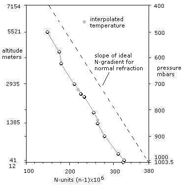
N-profile of refractive index
gradient for Hemsby radiosonde
14:0201Z 1956
It is always possible that anomalous refractivity gradients may exist in narrow layers unsampled by the radiosonde data-points. Such may be hinted at, for example at about 1385 m. A sharp enough clear air discontinuity, whatever the direction of the gradient, could cause forward scattering. (See Section d. below.)
b.) Sidelobe Returns & Multiple Reflections
Under certain conditions both sidelobe echoes and reflections can produce multiple returns from single targets. If the cluster of echoes could be ascribed to a single target, or a much smaller group of targets, then some of the difficulties associated with certain hypotheses could be reduced. A lone helicopter for example, perhaps unlit, might conceivably have escaped detection from the ground at Bentwaters and from the search aircraft.
A target painted by the main beam can also be swept by subsidiary radiation lobes as the the antenna rotates, resulting in echoes preceding and following the passage of the main beam. These are displayed at the true bore-sight azimuth of the antenna at the time of reception, causing a group of separated echoes to appear on the scope corresponding to the number of discrete lobes. This mechanism fails to account for the targets for several reasons.
The subsidiary echoes would be weak relative to the main-beam return from the same target, since the antenna gain falls sharply in azimuth away from the bore-sight. The first sidelobe might be, say, -30 db below the main beam, or 1/1000 of the radiated power, and thus could not paint an echo of even approximately comparable strength. A related problem is the range to which the targets were displayed, appearing as a cluster out to 40 miles or about 70% of the maximum range of the set: The absolute intensity of first sidelobe returns would be at best very low at such ranges, and those due to other minor lobes would almost certainly fail to exceed the receiver noise level. Even if such returns could be displayed their number would be much fewer than 15+, and most importantly sidelobe echoes are disposed in an arc to either side of the main beam return and at the same displayed range, in contrast to the essentially radial scatter of the targets observed.
Considered alone, the "triangular formation" at the head of the cluster could, with a deal of generosity, be interpreted as an arc, and thus could be somewhat similar to the characteristic morse letter "R" (dot-dash-dot) which operators know as the main beam return with its two flanking sidelobes. But the resemblance is strained: The report of a "triangular formation with an estimated 1800 feet separating each object in this formation" implies a displayed range differential on the order of 1000' (about twice the resolution), and the azimuthal separation therefore cannot be much more than the practical width of the main beam (about 2.3°) which obviously is a far smaller angle than that subtended by its first sidelobes.
Multiple reflections can occur between an aircraft and an efficient ground reflector, or between two or more aircraft, generating spurious moving targets whose behaviour is determined by the changing reflection geometry as one or more of the reflectors move relative to one another and the antenna. The strength of such ghost echoes is proportional to the efficiency of the reflectors, their orientation and their proximity to one another, whilst the number of echoes will depend upon the number of primary or secondary reflectors.
Radially moving ghosts are usually a result of situations in which a ground target is the first of two reflectors, so that the ghost is restricted to the azimuth of the ground reflector. But this geometry is ruled out by the motion of the targets between reciprocal azimuths. A radially moving aircraft scattering energy to a secondary ground reflector will produce a radially moving ghost at a greater displayed range proportional to the distance between the two reflectors. An array of secondary reflectors could conceivably generate several ghosts which would be displayed behind a radially approaching aircraft or ahead of a radially receding aircraft. But there are two conditions which are mutually inconsistent in terms of the behaviour of the Bentwaters targets:
1) The separation of aircraft and ghost echo will change as the aircraft approaches and recedes from the reflectors, reducing to near zero for example if the aircraft flies low over the reflectors; and
2) at no time can the ghost be displayed at a range from the antenna closer than the real range of the ground reflectors from the antenna.
It is therefore geometrically impossible for an aircraft to generate multiple ghosts from the same array of ground reflectors if a) the separation between aircraft and ghosts must remain constant and b) the ghost track is displayed between ranges as close as several miles and as far as several tens of miles. The responsible aircraft (which ex hypothesi must be an efficient reflector within the radiation pattern) could therefore not be one of the targets reported but would present as a quite separate and much stronger target moving more slowly behind or more rapidly ahead of the cluster on the same radial heading. This relationship would be especially notable. Both the array of secondary reflectors (near the radar site to allow for close displayed proximity on reciprocal headings) and the aircraft (overflying the site) would also be extremely unlikely to efficiently generate ghosts at opposite scope azimuths when the aspect of the aircraft is altering (in plan) by 180 degrees. The disposition of the ghost targets would also be symmetrical about the scope centre in such a case, and any pattern on the range axis would be inverted as the echoes crossed between sectors. It is moreover not possible for such ghosts from an aircraft as primary reflector to show separation in azimuth.
A stationary ghost can occur if the aircraft is approaching the reflector on a radius away from the antenna in level flight and the total path length therefore remains roughly constant. If the reflector is at 40 miles (coincident with the point of merger and stationarity in this case) a ghost will be displayed stationary at about 40 miles, but this cannot be the same reflector or array of reflectors responsible for multiple ghosts during the aircraft's radial approach since its ghost could not be displayed closer than 40 miles. On the other hand the array of reflectors responsible for the multiple ghosts could not produce a stationary, merged ghost at 40 miles: As has been shown, multiple ghosts require multiple ground reflectors, which would have to be at significantly different ground ranges resulting in path lengths differing by 6-7 miles (12-14 miles round trip), this being the target spread on the range axis, and thus the closest possible separation of the ghosts as the aircraft overflies the reflectors will be two orders of magnitude greater than the range resolution of the set. In other words, multiple targets due to multiple ground reflectors cannot simultaneously merge with the primary target and with one another. At least two completely independent reflection geometries involving completely different sets of reflectors are therefore required to produce these two behaviours.
The ghost hypothesis thus runs into problems at every turn, and clearly an attempt to construct a workable model would quickly become absurd, particularly in view of the fact that even a single ghost echo persisting for a short time is a rare event. Reflections between several airborne targets are possible in principle but are not considered further, save to say that the radar indication of several airborne objects is what we are trying to explain away, that none of the problemmatical features of the observation are seriously addressed by assuming effects of such extreme improbability, and that the consistency of the targets over time makes any ghost echoes extremely unattractive.
In summary, multiple reflections or sidelobe returns are not adequate to explain any of the central features of the track.
c.) Radio Frequency Interference/Deception Jamming
Accidental RFI can in principle cause false moving targets (see discussion of Tracks A, B & C.). A pulse of interference entering the system could feed a false signal amplitude to the cathode causing a spot to be painted on the tube phosphor at any point on the display, and a burst of 1 microsecond pulses at a synchronous PRF could generate an apparent "echo" during one sweep. Such an "echo" displaced scan-to-scan could, as we have seen, simulate returns from a moving target.
A second possibility arises when the input PRF is asynchronous. If the interpulse time is very short in relation to the PPI trace time then a number of spots would be distributed radially along one trace over a distance determined by the duration of the burst. Thus ten 1-microsecond pulses arriving 7 microseconds apart could be displayed as a radial line of 10 spots which, for a trace time of 742 microseconds corresponding to 60 nm range, would be spread evenly over a displayed range of about 6 miles. A PRF on the order of 7 microseconds would not however correspond to any typical radar emitter (the most likely source of cyclic 1-microsecond signals in the CPN-4 bandwidth) since it would permit a useful range of only about 8-900 metres, and even modern very-shortwave ASMI (Airfield Surface Movement Indicator) radars need an unambiguous range on the order of 10 times this figure. Nor could the report of "targets" separated in azimuth be explained in this way.
However, if the PRF is slightly longer than the PPI trace time then the input pulse train could generate spots on successive traces, and the resulting line of spots might only be slightly skewed due to the very small azimuth angle subtended by a small number of trace lines.
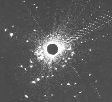
Unprocessed real-time display of high-power L-band radar
Range 120 miles. Shows aircraft returns (bright arcs), weather clutter (SW sector), system noise (random speckles) and interference (radial dots). The plate was exposed for one antenna revolution. Note the patterns of signals to the SE resembling the hypothetical pulse trains described in the text. Note also dissimilarity to normal aircraft targets. (From Cole 1985.)
Let us suppose an S-band receiver with a PRF of 1300 Hz, a scan period of 4 seconds and an unambiguous range of 742 microseconds or 60 n.miles (similar to the CPN-4). Let us also suppose an S-band transmitter with a PRF of 1340 Hz, a scan rate of 4 seconds + 2.47 microseconds, and an unambiguous range of 747 microseconds. One degree of transmitter beamwidth passing the receiving antenna at about 15 rpm in about 0.01 second would paint 13 spots displaying over 13 PPI traces subtending about 0.9° of azimuth in a near-radial alignment, covering about 5 miles of displayed range and moving radially outward at a displayed speed of about 150 knots, the pattern rotating and spreading only very slightly due to the constant angle subtended at the scope centre. Such an input could be due to radar energy spilling into the system from a similar radar due to unusual propagation conditions, the neighbouring radar's output being discretely "sampled" by a highly anisotropic duct as its beam swept towards the receiving antenna.
Range (miles)
Possible appearance of hypothetical train of 13 one-microsecond pulses at 1340 Hz displaying over 13 consecutive PPI traces on a 1300 Hz radar scope. Gain in displayed range of the pulse pattern is about 150 knots.
In practice things are unlikely to be quite so neat, and this model is of course only one of numerous possible models with somewhat similar outcomes; it is therefore quite possible that slightly different periodicities and more complex sampling of the input could create more complex - but still discrete - moving patterns. Such speckle patterns can in fact quite often be observed on unprocessed primary displays (see above) in interference conditions, although rarely in isolation.
The essential difficulty with this hypothesis is that it requires the operator to be totally inexperienced in interpreting the PPI. The bright target arcs of normal aircraft returns in no way resemble the single-trace point images produced by this mechanism, and it is inconceivable that T/Sergeant Whenry, evidently an experienced operator assessed by the 81st Fighter Bomber Wing Air Targets Officer as "usually reliable", would describe such an effect as a group of "normal targets". Further, the initial appearance of the targets to the SW, closing range from the opposite sector, cannot be explained on this hypothesis without assuming very fortuitous fluctuations in the scan rate of one or both interfering antennas.
The periods of stationarity are a related problem, since although one such episode - complete with simulated target closure and brightening due to spot integration - could be explained by assuming a minute fluctuation in the input PRF which brings the two periodicities precisely into phase, the subsequent movement of the now-integrated spot cannot be explained without an additional change in relative scan rate, and the final off-scope motion at a large angle to the earlier radial heading - after still another stationary episode - introduces yet another discontinuous change in relative scan rate, PRF synchrony being exactly preserved meanwhile. This set of demands is far too complex to be satisfied by chance interceptions of different consecutive signal sources, and unintelligible in terms of the cyclicities of any single emitter.
The detailed reported disposition of the targets poses further problems. The regular pulse emission from a radar would not appear as an "irregularly scattered" group of spots on the range axis preceded by a compact triangular "formation", although it is conceivable that that some superimposed cyclicity (due perhaps to intermodulation effects) might, when pulses are displayed over several adjacent trace radii with each scan, create an effect which could be so interpreted. A more complex spot pattern could be produced by transmissions of coded pulses from some type of installation other than a radar (notwithstanding the difficulty of a transit across the scope-centre) such as a navigational system. A continuous-wave system like the Decca Navigator is ruled out. Loran, which was also in use at this time, is pulsed but its pulse length of about 40 microseconds and PRF of 20-35 Hz are entirely inappropriate. Loran, furthermore, does not operate in the microwave band. ILS beacons are ruled out for similar reasons.
The probability of spurious internal signals generating such targets should be addressed in the light of the above discussion and that found here (Section b.), where the diametric transit of fast tracks A, B & C was considered. In the case of Track D we are concerned with a pattern of targets, and although the detail of the report is arguably inadequate to certify that the the anisotropic distribution of the targets was the same when tracked in the SW sector as when tracked into the NE sector this is obviously tacitly implied by omission. Such an asymmetry about the scope centre makes additional extraordinary demands on the input signal pattern, requiring the display product to be inverted along the range axis simultaneously with a halving of the input "scan" period to synchronise with the ½-rotation period of the receiver. (This clearly also applies to remote RFI.)
Moreover, even if the specific "formation" was only noticed in the NE sector, the fact that the targets exhibited a sensible angular separation implies a further order of complexity. A repeated pattern of signals with a fixed relationship to the PPI trace period would result in a divergent pattern of targets as displayed range increased. The reported separation of the 3 targets in the lead triangle was 1800', corresponding to 1-2° of the scope or about 7-14 traces for a 12000' separation at a displayed range of 10 miles; by the time the pattern had moved out to 40 miles this separation would have widened fourfold to 4-8000'. This divergence is in contrast to the implication of the report that separation was consistent to the point of convergence of the targets at 40 miles. In other words the progression of the target formation across the scope is constant relative the range axis (out to 40 miles) but during this time has an extremely complex relationship to a changing set of trace radii.
The probability of all the various systemmatic relationships being fulfilled simultaneously by an internal noise source which would either be essentially random or related in some simple way to the pulse or scan characteristics of the set would appear to be so remote as to be essentially nil.
Jamming and decoy techniques use both physical and electronic methods. Physical methods in use in 1956 would have been electronic countermeasures (ECM) expendables such as radar chaff, "window" and rope. These are clouds of metallised filaments dispensed from aircraft to blind or confuse enemy radars. The filaments are windborne and subject to some of the arguments discussed in connection with balloons with the qualification that they are not buoyant and would rapidly lose speed, blooming and dispersing - as they are designed to do - in a very short time. The EM smoke-screen they create in no way resembles any of the target behaviour observed.
MIT physicist Philip Morrison remarked to the AAAS UFO Symposium in 1969 with reference to aspects of this and other "interesting" radar-visual cases:
Perhaps the time has not yet come when we can do this, but we need eventually an accounting from high in the military heirarchy, concerning more of the far-flung systems that organisation operates. We need to know more about unusual drones and deliberate "spoofing" of all kinds. [Morrison 1972]
Electronic spoofing is considered in detail in Analysis of the Bentwaters Fast Radar Tracks, Sect. b., and in Analysis of the Intercepted Targets over Lakenheath, Track E, Sect. h. The CIA's Project Palladium [Poteas 1998], active from about 1962, might conceivably have had an historical precedent. But such hypotheses are impossible to test. The time still has not come, and probably will never come, when records of every classified historical project of this nature are in the public domain.
Unconventional aircraft, or remote drones related to some known operational RPV/decoy programmes such as the ADM-20A Quail - a free-flying pilotless ECM decoy carried by USAF B-52s and first deployed in 1960 - are conceivable explanations of these targets [see: Gunston 1983]. Such programmes are today numerous and many remain highly classified. But a multiple long-duration decoy system of which there appears to be no historical record seems implausible. Aircraft - conventional or not; combined with remote expendable decoys or not - seem unlikely in view of earlier arguments. It is difficult to set limits to the types of false target behaviour that could today be generated by computer-controlled deception jamming; with an analogue primary radar in 1956, however, technological possibilities were far more restricted. To generate a single spurious echo in one scope sector is one thing; to generate an asymmetrical pattern of spurious echoes moving between opposite scope sectors is quite another, and would require a degree of sophistication that seems at least implausible.
In summary, it is possible that RFI or internal noise sources might generate discrete patterns of moving spots which could be misreported as clusters of unusual "targets" by very inexperienced operators in some circumstances. This hypothesis seems worthy of further study, but its value in the present instance appears highly doubtful. The generation of a diametrical track of convincing "targets" by deception jamming techniques is theoretically possible but not a very attractive explanation.
d.) Partial Reflection due to Moving Waves on Elevated Layers
The simple partial reflection model predicts that as the wave propagates over the layer surface at wind speed the reflected ground echo moves across the PPI in the same approximate direction. Since the radar displays slant range according to the total out-and-back path length of the reflected signal, displayed range will always be twice the true slant range to the moving wave, so that the "phantom" location of the echo is moving at twice the speed of the wave and at twice its altitude.
Geometry of reflections due to moving waves on an inversion surface
In the present case Klass [1974], following Thayer [1971], has argued that winds were from the SW blowing at about half the reported speed of the echoes, which also moved from the SW. There are suggestive similarities to this model, but also significant discrepancies.
Surface winds recorded by the Bentwaters Weather Detachment for the period 2100Z-2200Z are indeed only 5° from the reported target heading, but windspeeds here of 5-10 knots are quite inappropriate. A reported target speed of 80-125 mph is approximately twice the speed of winds at about the 10-16,000' level, 39-55 knots from 260° which is about 35° away from a reported target heading SW-NE. The Met. Office Aerological Record of upper winds from the 2000Z Hemsby radiosonde shows the same pattern with 210° surface winds at 10 knots and stronger upper winds generally varying between 250°-270°.
This 35° mismatch between a 225° target motion and winds-aloft is not necessarily outside the range for atmospheric phenomena, which typically do have a component of motion at an angle to the wind. Nevertheless it is not insignificant and should not be imported without discussion. The more so because this error-angle increases to 80° during the reported northerly motion of the integrated target cluster off-scope at 2155 from a position 45-46 miles NE of Bentwaters:
The large object then moved N.E. approximately 5 or 6 miles then stopped its movement for 3 to 5 minutes then moved north disappearing off the radar scope.
This final leg would be some 20 miles long, corresponding to 180 paints in 12 minutes for a 100 mph target, long enough perhaps that the reported N heading should be considered potentially well-observed. At Bentwaters all winds above the surface were steady from 260° up to the highest level measured at 50,000'. The fit is actually rather worse than this if we consider the radiosonde data for Hemsby some 40 miles NNE of Benwaters - and therefore much closer to this portion of the track - in the light of the general synoptic development. The 2000Z radiosonde shows 10,000' winds from 260°, comparable to the Bentwaters data, and later releases at 0201Z and 0800Z indicate mid-level winds veering northerly towards 270° and 280° during the night, emphasising that the direction of the 80° 'error' for this track is opposite to the direction of the anticlockwise cyclonic circulation in the trail of the depression moving NE over the North Sea.
As mentioned, the general conditions are not necessarily unfavourable for stratification, even though weather had been coolish and breezy with daytime temperature maxima of 19-20°C . The night-time temperature/humidity vertical profiles for Hemsby show no low-level temperature inversion below the tropopause, but there is a subrefractive zone associated with surface humidity which could have a sharp upper boundary. There is also a discontinuity in relative humidity at about 5000 feet and the expected signs of strongly-developed stratification at the tropopause above the 30,000' level. As mentioned in Section a. above, the lower feature could be associated with a sharp refractivity gradient giving rise to the possibility of partial reflection, but there is no direct evidence of this in the N-profiles. Moreover, balloon releases at Bentwaters, Hemsby and Lakenheath all indicate that winds in the correct range to explain the target speeds only occur above roughly twice the altitude of the higher of these two levels. This leaves the possibility of reflections from discontinuities associated with the temperature inversions above 30,000'.
Now obviously it is geometrically impossible, in principle, for a ground return by partial reflection from a tropopausal layer to reach the receiver by a ray path shorter than 60,000', or about 11 miles; and in practice, because reflection does not occur at normal but rather at grazing incidence, this path length will be much longer. Therefore unlike reflections from a low-level layer, first-trip reflections from a tropopausal layer will always display at many miles range from the centre of the scope. It is possible for partial reflection to occur at suitably low grazing elevations from an efficient layer if the signal is returned from extreme distance beyond the unambiguous range as a multiple-trip echo. Such an echo could be displayed spuriously close to the scope centre, appearing as a nearby target. However this hypothesis is inconsistent with the evidence in this case for two related reasons.
The first is the relationship between displayed range and signal intensity described in IR-1-56: The 12-15 targets were tracked "clearly" at ranges less than 8 miles, appearing "as normal targets on the GCA scope", but then "faded considerably" as they receeded beyond 14 miles. The intensity of a signal returned from a distant ground target by a partially reflecting layer exhibits the opposite of this behaviour, being greatest at small grazing angles and dropping as the angle increases toward the normal. Typically this results in signal loss when the echo closes to displayed ranges of some miles and the reflected power drops below the noise level of the receiver, but the important point is that this relationship is a constant of the geometry, portable into different situations independently of scale.
The second point is that even though a first-trip partial reflection echo might disappear in one scope sector and then reappear in the opposite scope sector in the manner of an aircraft entering and leaving the zenithal radar shadow (albeit that its strength of presentation would then improve as displayed range increased and the grazing angle narrows, contrary to the trend of attenuation just described) a multiple-trip echo cannot do this, which rules out grazing-angle forward scattering returns from a possible tropopausal layer.
To discuss the range/attenuation issue first: A rough quantitative illustration is possible here from the operator's estimate of equivalent target cross-section at a known range. Attenuation of a partially reflected signal occurs in inverse proportion to the 6th power of the cosecant of the elevation angle (the actual angle of elevation and altitude are irrelevant since the relationship is one of fixed indirect proportionality to elevation above datum), which enables an order-of-magnitude estimate to be made of the relative spot-brightness to be expected at different PPI ranges.
According to IR-1-56 the cluster of targets appeared to merge into "one very large object" at a range of 40 miles, the combined assemblage yielding an integrated return "several times larger than a B-36 aircraft". Now the radar cross-section of an aircraft is dramatically dependent on aspect, reflectivity head-on and side-on differing by a factor of as much as 100 [Skolnik 1962]. Cole [1985] reports reflectivities for a twin-engined jet of 5-10 m2 head on or 100-1000 m2 side-on, and for a 4-engined jet of 20-50 m2 head-on or 1000-2000 m2 side-on. The B-36, in terms of plan area, wingspan, mass and number of engines (6 prop pushers and 4 jets in underslung pods) was one of the largest production aircraft ever built. However, plan area is of small account when we are considering reflectivity at low angles of elevation, and side-on the B-36 might have a geometric cross-section (which is related to but not the same as radar cross-section) perhaps 50% that of a large-bodied commercial jet such as a 747. Applying this proportionality to a tail-on aspect (bearing in mind that the comparison is in terms of a target receeding roughly in line of sight from the antenna) would suggest a figure of perhaps 10-25 m2, to represent which we shall assume a figure of 20 m2. However this figure would be greatly enhanced due to the large swept area of the six propellors, and a single 1.5-meter prop blade (say) would sweep an area of more than 7 m2. A total figure of 50 m2 might well be conservative. In addition the operator estimated a presentation "several times" the strength of a B-36 return, so that a reasonable rough estimate might be 200 m2 or so for the cross-sectional equivalent signal reflected back to the receiver at a displayed range of 40 miles. (Note that true slant range to the inversion layer would be 20 miles, but this is unimportant since the proportionality is preserved.)
Assuming that attenuation occurs only according to the ideal curve, and that the strength of the echo at 40 miles is due solely to the summed reflectivities of the 15-or-so individual zones now merged below the limit of PPI resolution, then the total returned energy distributed among the 15 targets would drop by about 18 db for each halving of range.* At a displayed range of 20 miles, therefore, the total energy would be (probably <) 1.56% of that reflected from the same layer at a displayed range of 40 miles (or roughly a factor 100 reduction in equivalent cross-section) which for the figure determined above yields an individual equivalent cross-section on the order of <0.2 m2 for each of the individual echoes. This factor falls below the minumum typical reflectivity of a poorly-aspected small jet fighter, 2-3 m2 [Cole 1985], by a factor of 10. At a displayed range of 10 miles each target has an effective cross-section of about 30 cm2 (roughly that of a pigeon), and at 5 miles the equivalent cross-section would be on the order of 0.5 cm2 (a small moth or bluebottle).
| * In fact these assumptions tend to flatter the partial reflection hypothesis because: a) the merging of such AP echoes commonly occurs due to the expansion or "blooming" of individual echoes, which would imply lower individual echo strengths prior to the point of merger; and b) because the presentation of the merged echo would probably appear stronger than the sum of its parts, being enhanced due to integration of the overlapping spots of excitation on the tube phosphor. |
Range (miles) below datum
elevation (°) above datum
Signal attentuation as a function of relative elevation and range, shown in terms of db and equivalent cross-section
Given the degree of approximation involved there is little point in carrying this exercise any further, but if the echoes were due to partial reflection from an elevated layer the ratio between the brightness of the signal displayed as the targets approached 40 miles and that displayed earlier in proximity to the scope centre should have been extreme. The close-in echoes at a few miles range should have been very marginal targets, particularly in view of the high noise figures (typically 10-12 db at S-band) prevalent in analogue circuits circa 1956. Yet no unusual close-in signal loss at all was reported. The targets were first observed to the SW of the site at a range of only 8 miles, appearing "as normal targets", which is to say that they were comparable to typical aircraft returns. They then appeared to overfly the site (spread out over a 6-7 mile area) and receded to a point about 14 miles NE before they "faded considerably".
Evidence of a positive (not an inverse) correlation between range and signal strength remains awkward for the partial reflection model, but, as indicated above, there is one way of getting around the report that the echoes diplayed at close range from the radar and therefore at a high (many degrees) angle of elevation.
We suppose that the beam is scattered from a point on the layer say 31 miles slant range from a radar with an unambiguous range of 60 miles, and a second-trip echo paints on the scope at 62-60 = 2 miles. When the scattering feature is 32 miles away the echo displays at 4 miles, and so on. This large slant range also allows the radar pulse to make a smaller incidence angle - perhaps the grazing angle for efficient forward scatter - even with a high altitude layer, and there is evidence of a significant temperature inversion at around 31,000'. This solves one problem but creates one even worse. The problem here is that targets were displayed crossing the scope from one sector into the opposite sector, and clearly the same scattering feature cannot have travelled about 60 miles between these reciprocal azimuths in less than about 35 minutes at the observed speed, or 70 minutes at the implied wind speed. And these figures are absolute minima for second-trip; they would be enormously multiplied for echoes delayed by longer trip times, so the more favourable the grazing angle the worse the time problem becomes. Moreover this objection applies to multiple-trip echoes whatever the altitude of the layer or whatever other propagation mechanism might be invoked. This leaves the possibility that one group of scattering features inbound on one heading faded just before a completely separate group of similar features appeared heading outbound on the opposite heading 60 miles away. The implausibility of this idea is not attractive.
In several respects, therefore, the simple partial reflection model seems inadequate to explain the motion and presentation, not to mention the apparently ordered and consistent disposition, of these targets. Other difficulties also remain to be discussed. Some, though not all, of these problems are possibly brought nearer to solution in Part 3.
© Martin Shough