GGS.5 Radar-Ranging Gyro Gunsight

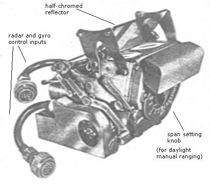
Three-quarter front view of GGS.5 from A.P.1275E Vol.1, Sect. 5 (A.L.84).
The gunsight is operated with the Mk.21 Air Interception radar. As described in detail here, the AI radar takes over automatic control of the range drive motor in the gunsight at a preset range. This is achieved by a voltage gate controlled by a Mk.3 Radar/Manual Control Unit. Two extracts from the relevant part of the AP, below, describe the operation of this circuit.
Extracts from AP 1275E, Vol.1, Sect. 5, Chap.5, Appendix 1
CONTROL UNIT, TYPE R.M. Mk.3
(NOTE: Fig.4 referred to in the text is missing from the original)
EXTRACT 1
Purpose
2. The incorporation of control unit, Type R.M. Mk.3 in the GGS. Mk.5 installation prevents interruption of the tracking process during the change over between manual and radar ranging. This change over is simply effected by operation of the twist grip.
Tactical operation
3. When the radar range equipment has been switched on, the pilot tracks his target with the twist grip at its minimum position (200 yd.) until he has completed any maoeuvres involving sharp turns. In this minimum position of the twist grip the current supplied to the range coils of the gyro is sufficient to prevent the gyro toppling in any sudden turn. As soon as he is tracking smoothly the pilot turns the twist grip to its maximum position (800 yd.) and the sight is automatically controlled by the radar equipment whenever the target range drops below 800 yd.
4. While the sight is being controlled by the radar equipment the twist grip is kept at its maximum position (800yd.) Should the pilot be forced to make sudden manoeuvres, he can regain immediate manual control of the sight by turning the twist grip back to its minimum position (200 yd.)
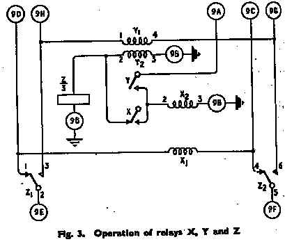
[NOTE: The meaning of the sense in which an automatic 'lock' may be acquired by the range gate circuitry of the electric gunsight, and broken by the loss of radar information due to sudden manoeuvres, should be clear from the above. The extract below describes in detail how the lock is automatically acquired with the help of the Mk.3 Control Unit and maintained by the range gate circuit.]
EXTRACT 2
Function of relays Xy Y and Z
11. Whenever the current flows from pin 9H to pin 9G (fig. 3) through coil Y, (para, 21), the radar equipment takes over control of the sight. The current in coil Yi operates relay Y and connects the 24-volt main supply via pin 9A to coil X2 which operates relay X, thereby supplying the same 24-volt supply to coil Y2 and relay Z.
12. The field in coil Y2 swamps the field in coil Y1 and locks relay Y in the energized position. This prevents any interruption of the supply to relay Z, when the current in Y1 ceases or changes direction during operation of the radar equipment (para. 22 and 23).

13. Until relay Z is energized, the sight is controlled by the pilot's twist grip (fig. 4), since contacts Z1 and Z2 connect coil C2, which controls the master relay C in the relay amplifier, via pins 11C and 11D to the wiper 5C of the potentiometer in the twist grip, and to the wiper 4C of the slave potentiometer in the range drive, while contact Z3 connects the F.B.M. potentiometer to the feedback circuit across the range drive motor (fig. 4).
14. When relay Z is energized, contacts Z1 and Z2 connect the coil C2 to the cathodes of V26B and V26A via pins 9C and 9D, whilst contact Z3 connects the F.B.R. potentiometer to the feedback circuit. The rotation of the motor in the range drive unit and, therefore, the range control mechanism in the sighting head is now determined by the current flowing between the cathodes of V26A and V26B (para. 22 and 23).
15. The wiper of the potentiometer in the twist grip is always connected to the wiper of the linear slave potentiometer through coil X1. While the radar equipment is in control, the twist grip is held at its maximum position (800 yd.). The wiper of the twist grip potentiometer is, therefore, at zero potential and current flows through coil X1 from pin 9C to pin 9D, i.e., from the wiper of the linear slave potentiometer to the wiper in the twist grip potentiometer. The field of coil X1 reinforces the field in coil X2 and ensures that the 24-volt supply is fed to relay Z and coil Y2.
16. If the pilot requires to gain manual control of the sight, he turns the twist grip to its minimum position (200 yd.). The wiper of the potentiometer in the twist grip is then at a potential of 24 volts and current flows through coil X1 from pin 9D to pin 9C, i.e., towards the wiper of the linear slave potentiometer. The field in coil X1 now opposes and overcomes the field in coil X2 . Relay X opens and the supply to relay Z and coil Y2 is broken.
Operation of V26 (fig. 5)
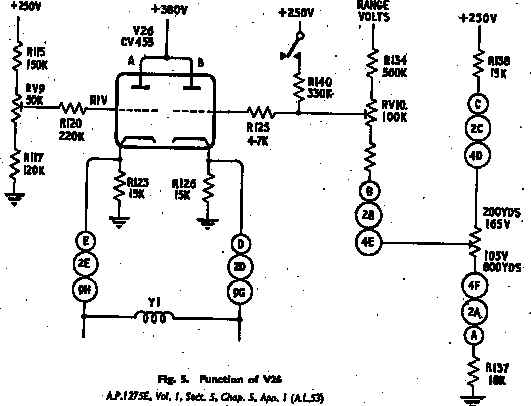
17. When the radar equipment is switched on, the grid of V26A is held at 111 volts by the divider chain R115, RV9 and R117: the grid of V26B is returned to two supplies, through R125, R140 and relay B2 to + 250 volts, and through R125, RVIO and R136 to + 165 volts picked off by the wiper of the log slave potentiometer, when it is at its minimum position (200 yd.).
18. These two supplies raise the grid of V26B to approximately 200 volts which raises the potential at the cathodes of V26B and V26A since they are connected by coil Y1, to approximately the same voltage. V26A, consequently, is cut off and V26B is conducting so that current flows through coil Y in the direction which holds relay Y open.
19. Relay B2 opens, whenever the radar equipment locks on. The grid of V26B is then supplied from the wiper of the log slave potentiometer, which is still at 165 volts (200 yd.), and from the range valve through R134. These two supplies are so designed that whenever the voltage values supplied by the range valve and the wiper of the log slave potentiometer represent the same range, the voltage on the grid of V26B is 111 volts. The voltage on the grid of V26B cannot, however, drop to this value so long as the log slave potentiometer is in its minimum position (165 volts at 200 yd.).
20. If the pilot now turns the twist grip to its maximum position (800 yd.), the wiper of the log slave potentiometer is also turned to the maximum position and only supplies 105 volts to the grid of V26B.
21. In conjunction with the continual decrease in voltage from the range valve, the potential on the grid of V26B drops. When the target range is exactly 800 yd. both the grids of V26 are at the same potential 111 volts. Consequently both cathodes are at the same potential and no current flows through coil Y1. As the target range further decreases, the voltage on the grid of V26B drops below 111 volts. With the consequent drop in the potential of the cathodes, V26A starts to conduct and current flows through coil Y1 from pin 9H to pin 9G, causing the range drive mechanism to be controlled by the radar equipment when the field in coil Y1 is strong enough to operate relay Y.

22. When relay Y operates, the potential across coil Y1 is also applied across coil C2 (fig. 4) since they are now in parallel. This biases the master relay C so that the motor in the range drive unit turns the range drive from 800 yd. towards 200 yd. As soon as the wiper of the log slave potentiometer picks off a voltage equivalent to the range supplied by the range valve, say 700 yd., both grids of V26 are at 111 volts; the current through coil Y1 ceases, and the master relay oscillates between the contacts of the slave relays. If the range further decreases, the same process is repeated.
23. Should the range increase, the voltage from the range valve increases and raises the voltage on the grid of V26B above 111 volts. The rise in the potential of the cathodes cuts V26A off and the current in Y, flows from B to A. This biases the master relay C in the opposite direction and causes the range drive to turn towards 800 yd. until the voltages supplied by the wiper of the log slave and by the range valve again represent the same range.
24. In figs. 3, 4 and 5 the following colour code and control unit code is used. Where pins are denoted by letter only, they refer to the appropriate connection from the Radar Ranging Unit.
Crown copyright material is reproduced with the permission of the Controller of HMSO and the Queen’s Printer for Scotland.